Background
Back in June 2024 I decided it was finally time to add wired ethernet throughout my townhouse, as part of a larger series of renovations.
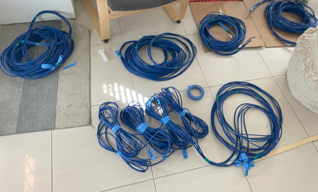
As part of this I put a small 6 RU networking cabinet into the garage to terminate the 24 additional ethernet runs I put in. This networking rack contains the following:
- Router [Ubiquiti EdgeRouter X]
- 24 Port Gigabit Switch [TP-link TL-SG1024DE]
- 8 Port PoE Gigabit Switch [TL-SG108PE]
- PSU
- 2 x 24 Port Patch Panels
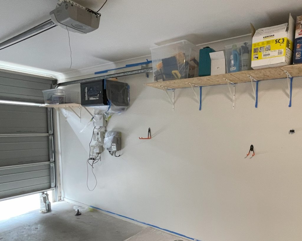
The garage remains reasonably cool, peaking at about 32 degrees celsius in the height of summer, however since I cheaped out on the Gigabit switch, it was only rated for 40 degrees operating. That didn’t leave much cooling margin so I knew I would need to add active cooling.
Of course, being just one of many things I was doing at the time I decided to take a bit of a shortcut on cooling – I left the sides off for ‘natural’ cooling and jerry rigged together an old 120 mm fan for the top of the rack. Job done? No way! But I decided I’d come back to it soon…
Well fast forward almost a year later and I figured it was time I should finally get around to building a fan controller and adding the fans.
Requirements
I had a number of specific requirements:
- Speed controlled fans to minimise noise and maximise fan life.
- Multiple sensors:
- Temperature sensors – including at least 2 sensors to ensure valid readings (1 primary, 1 backup).
- Humidity sensors – as there is a dryer in the garage (along with the rest of the laundry) and when that is running it gets steamy.
- Multiple fans:
- 1 x 120 mm exhaust fan (top of rack).
- 4 x 80 mm intake fans (mounted in 2 RU blanking panel, bottom of rack).
- Embedded, microcontroller based solution. Cheap to make and customise.
Fan Selection
For the fan selections I am looking for the following things:
- Available from www.mouser.com – the primary distributor I use.
- 12 V compatible (single power supply solution).
- PWM speed control.
- Tachometer for speed readout.
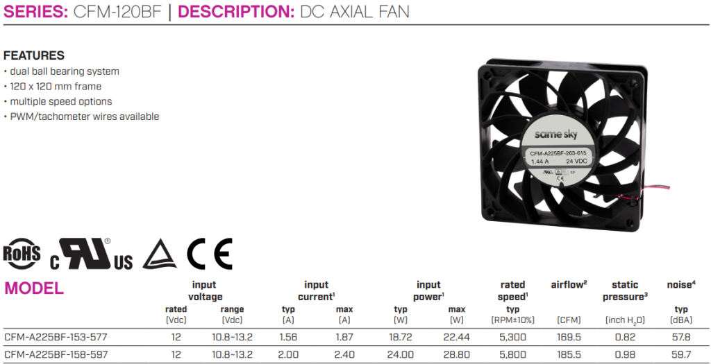
Exhaust fan – 120 mm
For the 120 mm fan I picked the CFM-A225BF-158-597-22 as an exhaust fan. This fan uses ~2.4 A max, and can move an impressive 185.5 CFM (cubic feet per minute in stupid units, ~ 5 m^3/minute in real units). That is running at a max speed of 5800 RPM and a sound level of 59.7 dBA – the sound level of a normal conversation. I suspect I won’t have to run this fan that hard.
This means for the selected enclosure (360 x 530 x 450 mm), we can exhaust the entire volume in just over 1 second. Not bad.
Overkill? Maybe. Lets do the maths.
According to those nerds at Stack Exchange, the required airflow (m^3/s) = (P*t)/(ΔT * D * SHC) where:
- P = Power [watts]
- t = Time [seconds]
- ΔT = Difference in Temperature [°C or K]
- D = Density of Air [kg/m^3]
- SHC = Specific Heat of Air [J/(kg*K)]
Lets say we need to cool switches, their power supplies etc (including allowing 100W for this project) ~ 350 W, have 8 degrees delta worst case (32-40), density of air is 1.16 kg/m^3 at 32 degrees and the specific heat is 1000. This results in 0.0378 m^3/s.
This gives us an airflow of 2.26 m^3/minute. So we have overrated by approx 50% volume. I am happy with that margin – I will be able to run my fans slow and silently.
Intake fans – 4 x 80 mm
For similar reasons as above I selected 4 x CFM8020BF-155-444-22 fans. These run at 5,500 RPM at 44 dBA max and move an impressive 53 CFM (~1.5 m^3/min). With all four running I can easily intake the maximum volume the exhaust fan can put out.
The only downside to these fans is that the datasheet lists the wire gauge at 28 AWG – which outside of the defacto standard sizes (12 – 26 AWG), so will have to consider that in their termination.
So that’s the hard part done right? Picked the fans! Will be moving on to power supply and cabling selection next time.
Leave a Reply